Printed Circuit Boards
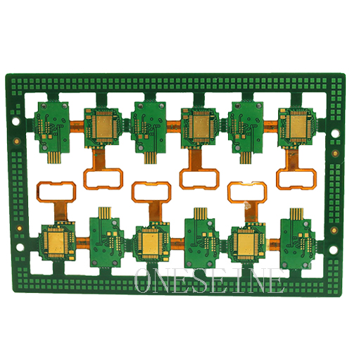
Rigid-flexible pcb 6 Layer PI FPC With ENIG/OSP Surface Manufacturing Process
- multilayer pcb
- rigid flex pcb
- FPC
- 6 layer pcb
- Product description: Rigid-flexible pcb 6 Layer PI FPC With ENIG/OSP Surface Manufacturing Process
Rigid-flexible pcb 6 Layer PI FPC With ENIG/OSP Surface Manufacturing Process
Quick detail:
Flex Material: Polyimide PI
Rigid Material: fr4
Surface finish: Immersion gold
Thickness:0.2MM
Copper weight: 0.5OZ
Delivery time: 3-5 days for sample order,7-9days for mass production
Layer:2
Product type: Rigid-flexible pcb
Package: inner: vacuum-packed bubble bag outer: carton box
Rigid-flexible pcb knowledge:
As the developing of FPC and PCB, have a combination of flex and rigid board. Therefore, the flex and rigid combination board, is a flexible circuit board and rigid circuit board, through the stack up and other processes, according to the relevant process requirements together to form a FPC characteristics and PCB characteristics of the circuit board.
Because the rigid-flexible pcb is FPC and PCB combination, the production of flex and rigid board should have both FPC production equipment and PCB production equipment. First, the electronic engineer draws the line and shape of the soft bonding plate according to the demand, and then sends the paper to the factory which can produce the rigid and flex bonding board. After the CAM engineer processes and plans the relevant documents, arranges the FPC production line. FPC, PCB production line to produce PCB, these two flexible and rigid board came out, in accordance with the planning requirements of electronic engineers, the FPC and PCB after a seamless pressure laminating machine, and then through a series of details of the link, the final process A combination of rigid-flexible pcb.
Flexible circuit part material
The base material is the flexible polymer film which provides the foundation for the laminate. Under normal circumstances, the flex circuit base material provides most primary physical and electrical properties of the flexible circuit. In the case of adhesiveless circuit constructions, the base material provides all of the characteristic properties. While a wide range of thickness is possible, most flexible films are provided in a narrow range of relatively thin dimension from 12 µm to 125 µm (1/2 mil to 5 mils) but thinner and thicker material are possible. Thinner materials are of course more flexible and for most material, stiffness increase is proportional to the cube of thickness. Thus for example, means that if the thickness is doubled, the material becomes eight times stiffer and will only deflect 1/8 as much under the same load. There are a number of different materials used as base films including: polyester (PET), polyimide (PI), polyethylene naphthalate (PEN), polyetherimide (PEI), along with various fluropolymers (FEP) and copolymers. Polyimide films are most prevalent owing to their blend of advantageous electrical, mechanical, chemical and thermal properties.
Rigid- flexible pcb board capability:
|
Item |
Technical parameters |
|
Layers |
1-6 |
|
Min. line width |
2/2mil |
|
Min. line space |
2/2mil |
|
Min. hole size |
Drill hole 0.1mm; Punch hole 0.4mm |
|
Max. aspect ratio |
7:01 |
|
Max. board size |
500*600mm |
|
Line width tolerance |
±0.015mm |
|
Hole size tolerance |
±0.05mm |
|
Hole position tolerance |
±0.05mm |
|
Outline tolerance |
±0.05-0.2mm |
|
ZIF tolerance |
±0.05-0.1mm |
|
Inner layer contraposition tolerance |
±0.08mm |
|
Board material |
Polyimide resin/ polyester and FR4 |
|
Base material thickness |
Polyimide resin (12.5um,25um,50um,75um,125um); Polyester(50um,75um,100um) |
|
Coverlay film thickness |
Polyimide resin (12.5um, 25um, 50um, 75um); Polyester(25um,50um) |
|
Copper thickness |
12um,18um,35um,50um,70um,105um |
|
Surface finish |
Immersion gold, OSP,etc |
|
Impedance control |
± 10% |
Rigid-flex circuits
Rigid-flex circuits are a hybrid construction flex circuit consisting of rigid and flexible substrates which are laminated together into a single structure. Rigid-flex circuits should not be confused with rigidized flex constructions, which are simply flex circuits to which a stiffener is attached to support the weight of the electronic components locally. A rigidized or stiffened flex circuit can have one or more conductor layers. Thus while the two terms may sound similar, they represent products that are quite different.
The layers of a rigid flex are also normally electrically interconnected by means of plated through holes. Over the years, rigid-flex circuits have enjoyed tremendous popularity among military product designer, however the technology has found increased use in commercial products. While often considered a specialty product for low volume applications because of the challenges, an impressive effort to use the technology was made by Compaq computer in the production of boards for a laptop computer in the 1990s. While the computer's main rigid-flex PCBA did not flex during use, subsequent designs by Compaq utilized rigid-flex circuits for the hinged display cable, passing 10s of 1000s of flexures during testing. By 2013, the use of rigid-flex circuits in consumer laptop computers is now common.
Rigid-flex boards are normally multilayer structures; however, two metal layer constructions are sometimes used.
Rigid-flexible pcb application:
Mobile phone
Key board and side buttons and so on
Computer with LCD screen
Motherboard and display
CD Walkman
Drive
NOTEBOOK.
Categories
Latest News
Contact Us
Contact: Ms Tracy
Phone: 0086 18682010757
Tel: 0086 18682010757
Add: Building9,Xinyuan Industrial Park,Tangwei,Fuyong,Baoan,Shenzhen,China
 Tracy
Tracy